


You have 0 items in your cart.

Features
- Frequency Range: 9kHz ~ 3GHz
- High Frequency Stability: 25ppb (0.025ppm)
- RBW: 10Hz ~ 10kHz in 1-3 steps, 10kHz ~ 1MHz in 10% adjustable steps
- Phase Noise: -88dBc/Hz @1GHz, 10kHz Offset
- Built-in Measurement Functions: Channel Power, N-dB bandwidth, OCBW, ACPR, SEM, TOI, CNR, CTB, CSO
- Built-in Spectrogram and Topographic Display Modes
- Gate Sweep Function
- 1Hz Resolution Marker Counter
- AM/FM Demodulation Analysis
- 886MHz IF Output for User’s Extended Applications
- Various Interface: USB Host/Device, RS-232, LXI, Micro SD, GPIB (Optional)
- 8.4" large TFT LCD display with SVGA resolution of 800 *600
- DVI-I Output for External Digital Display
- Built-in Preamplifier, 50dB Attenuator, and Sequence Function
- Optional 6GHz Power Sensor, Tracking Generator, Battery Back
Description :
|
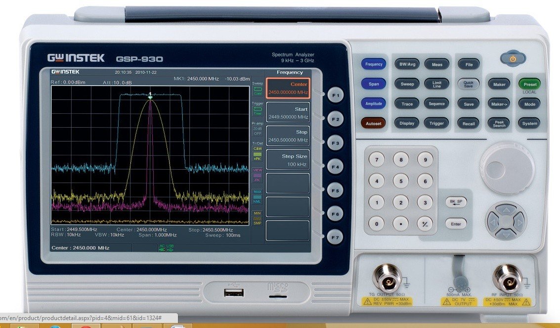
GSP-930 is a 3GHz Spectrum Analyzer designed upon a new generation platform. The high stability, large screen display, light weight and compact size of GSP-930 benchmark a new standard for 3GHz spectrum analyzer in the market. Its advanced features, Spectrogram and Topography, greatly expand the application range and elevate the importance of a spectrum analyzer in the role as the irreplaceable RF analysis instrument.
GSP-930 provides a high frequency-stability of 25ppb (0.025ppm) and a very low noise floor of -142dBm (Pre-amplifier on) as the high sensibility measurement base. The flexible selection among 58 RBW ranges along with Spectrogram and Topographic features enable GSP-930 to capture and display transient, drifting and hopping signals in detail. The mixture of frequency domain information and time domain information facilitates the tracing of RF signal variations over time. Other remarkable features like Spectrum Emission Mask (SEM), Power Measurements, AM/FM Analysis and TOI/CNR/CSO/CTB measurements, make GSP-930 a useful instrument right fit into a broad range of applications. The user friendly design of GSP-930 helps reduce user’s stress and anxiety in using a high-tech instrument. To help user easily get access to the regulations and definitions of the measurement terms under current operation, the built-in On-Screen-Help provides definition descriptionon the screen to guide user through measurement processes without checking into documents. The widely used Icons on the display clearly indicate the current setting and operation status of the product, allowing user to handle the measurement scenario all at a glance. The wake-up clock automatically turns on the power of GSP-930 at user’s pre-set time, which can be used to warm up the instrument in advance before the measurements are made to ensure the accuracy of measurement results. The Pass/Fail Limit function allows user to perform repetitive go/no-go measurements by template inspection instead of time-consuming value reading. The Sequence function provides an easy programming feature for user to edit and run measurement routines on GSP-930 screen without the need of a PC. GSP-930 is equipped with various interfaces, including LXI, USB, RS-232 and GPIB (optional). The IVI driver is available for the remote control software development by means of LabVIEW or LabWindows/CVI. A Micro SD slot and a USB Host interface enable the memory size expansion for mass data storage. An IF output (886MHz) is provided as the intermediate frequency signal of RF inputfor users to develop their own applications. Carrying abundant communication interfaces, user-friendly operation, large screen display, light weight, compact size, and battery power operation(1), GSP-930 is developed upon a high-tech platform to provide ultimate customer benefits. Remark (1): Battery pack is optional. |
|
|||||||||||||||||||||||||||||||||||||||||||||||||||||||||||||||||||||||||||||||||||||||||||||||||||||||||||||||||||||||||||||||||||||||||||||||||||||||||||||||||||||||||||||||||||||||||||||||||||||||||||||||||||||||||||||||||||||||||||||||||||||||||||||||||||||||||||||||||||||||||||||||||||||||||||||||||||||||||||||||||||||||||||||||||||||||||||||||||||||||||||||||||||||||||||||||||||||||||||||||||||||||||||||||||


Specification :
The specifications apply when the GSP-930 is powered on for at least 30 minutes to warm-up to a temperature of 20°C to 30°C, unless specified otherwise.
| Frequency | |||
| Frequency | |||
| Range | 9 kHz to 3.0 GHz | ||
| Resolution | 1 Hz | ||
| Frequency Reference | |||
| Accuracy | ±[(period since last adjustment X aging rate) + stability over temperature + supply voltage stability | ||
| Aging Rage | ±2 ppm max. | 1 year after last adjustment | |
| Frequency Stability over Temperature | ±0.025 ppm | 0 to 50 °C | |
| Supply Voltage Stability | ±0.02 ppm | ||
| Frequency Readout Accuracy | |||
| Start, Stop, Center, Marker | ±(marker frequency indication X frequency reference accuracy + 10% x RBW + frequency resolution1) | ||
| Sweep points | 601 | Span > 0 | |
| 6 to 601 | Span = 0 | ||
| Marker Frequency Counter | |||
| Resolution | 1 Hz, 10 Hz, 100 Hz, 1 kHz | ||
| Accuracy | ±(marker frequency indication X frequency reference accuracy + counter resolution) |
RBW/Span >=0.02 ;
Mkr level to DNL>30 dB
|
|
| Frequency Span | |||
| Range | 0 Hz (zero span), 100 Hz to 3 GHz | ||
| Resolution | 1 Hz | ||
| Accuracy |
|
||
|
Phase Noise
|
|||
|
|
Offset from Carrier
|
|
Fc =1 GHz; RBW = 1 kHz, VBW = 10 Hz;Average ≥ 40
|
|
10 kHz
|
<-88 dBc/Hz
|
Typical2
|
|
|
100 kHz
|
<-95 dBc/Hz
|
Typical
|
|
|
1 MHz
|
<-113 dBc/Hz
|
Typical
|
|
| Resolution Bandwidth (RBW) Filter | |||
| Filter Bandwidth | 10 Hz to 3 kHz in 1-3-10 sequence |
-3dB bandwidth
subtotal: 6 filters
|
|
| 10 kHz to 1 MHz, increment in 10% step |
-3dB bandwidth;
min. RBW = 10 kHz @ zero span
Subtotal: 49 filters
|
||
| 200 Hz, 9 kHz, 120 kHz | -6dB bandwidth | ||
| Accuracy | ± 8%, RBW ≥ 750 kHz |
|
|
| ± 5%, RBW < 750 kHz | Nominal | ||
| Shape Factor | < 4.5:1 | Normal Bandwidth ratio: -60dB:-3dB | |
| Video Bandwidth (VBW) Filter | |||
| Filter Bandwidth | 1 Hz to 1 MHz in 1-3-10 sequence | -3dB bandwidth | |
|
|
|||
| Amplitude | |||
| Amplitude Range | |||
| Measurement Range | 100 kHz to 1 MHz | Displayed Average Noise Level (DANL) to 18 dBm | |
| 1 MHz to 10 MHz | DANL to 21 dBm | ||
| 10 MHz to 3 GHz | DANL to 30 dBm | ||
| Attenuator | |||
| Input Attenuator Range | 0 to 50 dB, in 1 dB step | Auto or manual setup | |
| Maximum Safe Input Level | |||
| Average Total Power | £ +33 dBm | Input attenuator ≥10 dB |
|
| DC Voltage | ± 50 V | ||
|
1 dB Gain Compression
|
|||
|
|
Total Power at 1st Mixer
|
> 0 dBm
|
Typical;Fc ≥50 MHz; preamp. off
|
|
|
Total Power at the Preamp
|
> -22 dBm
|
Typical;Fc ≥50 MHz; preamp. on
|
|
|
|
|
mixer power level (dBm)= input power (dBm)-attenuation (dB)
|
| Displayed Average Noise Level (DANL)4 | |||
| Preamp off | 0 dB attenuation; RBW 10 Hz; VBW 10 Hz; span 500 Hz; reference level = -60dBm; trace average ≥ 40 | ||
| 9 kHz to 100 kHz | < -93 dBm, |
|
|
| 100 kHz to 1 MHz | < -90 dBm - 3 x (f/100 kHz) dB | ||
| 1 MHz to 10 MHz | < -122 dBm | ||
| 10 MHz to 3 GHz | < -122 dBm | ||
| Preamp on | 0 dB attenuation; RBW 10 Hz; VBW 10Hz; span 500 Hz; reference level = -60dBm; trace average ≥ 40 | ||
| 100 kHz to 1 MHz | < -108 dBm - 3 x (f/100 kHz) dB |
|
|
| 1 MHz to 10 MHz | < -142 dBm | ||
| 10 MHz to 3 GHz | < -142 dBm + 3 x (f/1 GHz) dB | ||
| [4] DANL spec shall exclude the Spurious Response | |||
| Level Display Range | |||
| Scales | Log, Linear | ||
| Units | dBm, dBmV, dBuV, V, W | ||
| Marker Level Readout | 0.01 dB | Log scale | |
| 0.01 % of reference level | Linear scale | ||
| Level Display Modes | Trace, Topographic, Spectrogram | Single / split Windows | |
| Number of Traces | 4 | ||
| Detector | Positive-peak, negative-peak, sample, normal, RMS(not Video) | Can be setup for each trace separately | |
| Trace Functions | Clear & Write, Max/Min Hold, View, Blank, Average | ||
|
Absolute Amplitude Accuracy
|
|||
|
|
Absolute Point
|
Center=160 MHz ; RBW 10 kHz; VBW 1 kHz; span 100 kHz; log scale; 1 dB/div; peak detector; 20 to 30°C; signal 0 dBm
|
|
|
|
Preamp off
|
± 0.3 dB
|
Ref level 0 dBm; 10 dB RF attenuation
|
|
|
Preamp on
|
± 0.4 dB
|
Ref level -30 dBm; 0 dB RF attenuation
|
| Frequency Response | |||
| Preamp off | Attenuation: 10 dB; Reference: 160 MHz; 20 to 30°C | ||
| 100 kHz to 2.0 GHz | ± 0.5 dB | ||
| 2.0GHz to 3.0 GHz | ± 0.7 dB | ||
| Preamp on | Attenuation: 0 dB; Reference: 160 MHz; 20 to 30°C | ||
| 1 MHz to 2.0 GHz | ± 0.6 dB | ||
| 2.0GHz to 3.0 GHz | ± 0.8 dB | ||
| Attenuation Switching Uncertainty | |||
| Attenuator setting | 0 to 50 dB in 1 dB step | ||
| Uncertainty | ± 0.15 dB | reference: 160 MHz, 10dB attenuation | |
| RBW Filter Switching Uncertainty | |||
| 10 Hz to 1 MHz | ± 0.25 dB | reference : 10 kHz RBW | |
| Level Measurement Uncertainty | |||
| Overall Amplitude Accuracy | ± 1.5 dB | 20 to 30°C; frequency > 1 MHz; Signal input 0 to -50 dBm; Reference level 0 to -50 dBm; Input attenuation 10 dB; RBW 1 kHz; VBW 1 kHz; after cal; Preamp Off |
|
| ± 0.5 dB |
|
||
|
Spurious Response
|
|||
|
|
Second Harmonic Intercept
|
|
Preamp off; signal input -30dBm; 0 dB attenuation
|
|
|
|
+35 dBm
|
Typical; 10 MHz < fc < 775 MHz
|
|
|
+60 dBm
|
Typical; 775 MHz ≤ fc < 1.5 GHz
|
|
|
|
|
|
|
|
|
Third-order Intercept
|
|
Preamp off; signal input -30dBm; 0 dB attenuation
|
|
|
> 1dBm
|
300 MHz to 3 GHz
|
|
|
|
Input Related Spurious
|
< -60 dBc
|
Input Related Spurious <-60dBc , Input signal level -30 dBm, Att. mode Auto; 20-30 degree C
|
|
|
Residual Response (inherent)
|
<-90 dBm
|
Input terminated; 0 dB attenuation; Preamp off
|
|
|
|||
| Sweep Time | |||
| Range | 22 ms to 1000 s | Span > 0 Hz | |
| 50 us to 1000 s | Span = 0 Hz; Min Resolution = 10 us | ||
| Sweep Mode | Continuous; Single | ||
| Trigger Source | Free run; Video; External | ||
| Trigger Slope | Positive or negative edge | ||
|
|
|||
| Frequency Range | 1 MHz to 3 GHz | ||
| Gain | 18 dB | Nominal | |
| (installed as standard) | |||
|
|
|||
| RF Input | |||
| Connector Type | N-type female | ||
| Impedance | 50 ohm, nominal | ||
| VSWR | <1.6 :1 | 300 kHz to 3 GHz; Input attenuator ≥ 10 dB | |
|
Power for Option
|
|||
|
|
Connector Type
|
SMB male
|
|
|
|
Voltage/Current
|
DC +7V / 500 mA max
|
With short-circuit protection
|
| USB Host | |||
| Connector Type | A plug | ||
| Protocol | Version 2.0 | Supports Full/High/Low speed | |
| MicroSD Socket | |||
| Protocol | SD 1.1 | ||
| Supported Cards | MicroSD, MicroSDHC | Up to 32GB capacity | |
|
|
|||
| Reference Output | |||
| Connector Type | BNC female | ||
| Output Frequency | 10 MHz | ||
| Output Amplitude | 3.3V CMOS | ||
| Output Impedance | 50 ohm | ||
| Reference Input | |||
| Connector Type | BNC female | ||
| Input Reference Frequency | 10 MHz | ||
| Input Amplitude | -5 dBm to +10 dBm | ||
| Frequency Lock Range | Within ± 5 ppm of the input reference frequency | ||
| Alarm Output | |||
| Connector Type | BNC female; Open-collector | ||
| Trigger Input/ Gated Sweep Input | |||
| Connector Type | BNC female | ||
| Input Amplitude | 3.3V CMOS | ||
| Switch | Auto selection by function | ||
| LAN TCP/IP Interface | |||
| Connector Type | RJ-45 | ||
| Base | 10Base-T; 100Base-Tx; Auto-MDIX | ||
| USB Device | |||
| Connector Type | B plug | For remote control only; supports USB TMC | |
| Protocol | Version 2.0 | Supports Full/High speed | |
| IF Output | |||
| Connector Type | SMA female | ||
| Impedance | 50 ohm | Nominal | |
| IF Frequency | 886 MHz | Nominal | |
| Output level | -25 dBm | 10 dB attenuation; RF input: 0 dBm @ 1 GHz; | |
| Earphone Output | |||
| Connector Type | 3.5mm stereo jack, wired for mono operation |
||
| Video Output | |||
| Connector Type | DVI-I ( integrated analog and digital) , Single Link | Compatible with VGA or HDMI standard through adapter | |
| RS232 Interface | |||
| Connector Type | D-sub 9-pin female | Tx,Rx,RTS,CTS | |
| GPIB Interface (Optional) | |||
| Connector Type | IEEE-488 bus connector | ||
| AC Power Input | |||
| Power Source | AC 100 V to 240 V, 50 / 60 Hz | Auto range selection | |
| Battery Pack (Optional) | |||
| Battery pack | 6 cells, Li-Ion rechargeable, 3S2P | With UN38.3 Certification | |
| Voltage | DC 10.8 V | ||
| Capacity | 5200 mAh / 56Wh | ||
|
|
|||
| Internal Data storage | 16 MB nominal | ||
| Power Consumption | <65 W | ||
| Warm-up Time | < 30 minutes | ||
| Temperature Range | +5 °C to +45 °C | Operating | |
| -20 °C to + 70 °C | Storage | ||
| Weight | 4.5 kg (9.9 lb) | Inc. all options (Basic+TG+GPIB+Battery) | |
| Dimensions | 210 x 350 x 100 (mm) | Approximately | |
| 8.3 x 13.8 x 3.9 (in) | |||
|
|
|||
| Frequency Range | 100 kHz to 3 GHz | ||
| Output Power | -50 dBm to 0 dBm in 0.5 dB steps | ||
| Absolute Accuracy | ± 0.5 dB | @160 MHz, -10 dBm, Source attenuation 10 dB, 20 to 30°C | |
| Output Flatness | Referenced to 160 MHz, -10 dBm | ||
| 100 kHz to 2 GHz | ± 1.5 dB | ||
| 2 GHz to 3 GHz | ± 2.0 dB | ||
| Output Level Switching Uncertainty | ± 0.8 dB | Referenced to -10 dBm | |
| Harmonics | < -30 dBc | Typical, output level = -10 dBm | |
| Reverse Power | +30 dBm max. | ||
| Connector type | N-type female | ||
| Impedance | 50 ohm | Nominal | |
| Output VSWR | < 1.6:1 | 300 kHz to 3 GHz, source attenuation ≥ 12 dB | |
|
|
|||
| Type | Average power sensor | Model: PWS-06 | |
| Interface to Meter | USB cable to GSP930 Front-Panel USB Host | ||
| Connector Type | N-type male, 50 ohm nominal | ||
| Input VSWR | 1.1: 1 | Typical | |
| 1.3: 1 | Max | ||
| Input Frequency | 1 to 6200 MHz | ||
| Sensing Level | -32 to +20 dBm | ||
| Max. Input Damage Power | ≥ 27 dBm | ||
| Power Measurement Uncertainty @ 25 °C |
-30 dBm to +5 dBm:
1 MHz to 3GHz: ±0.10 dB typical
3 GHz to 6 GHz: ±0.15 dB typical
1 MHz to 3GHz: ±0.15 dB typical
3 GHz to 6 GHz: ±0.15 dB typical
1 MHz to 3GHz: ±0.20 dB typical
3 GHz to 6 GHz: ±0.20 dB typical
|
±0.30 dB max.
±0.30 dB max.
±0.30 dB max.
±0.40 dB max.
|
|
| Power Measurement Uncertainty @ 0 to 25 °C |
-30 dBm to +5 dBm:
1 MHz to 3GHz: ±0.25 dB typical
3 GHz to 6 GHz: ±0.25 dB typical
1 MHz to 3GHz: ±0.20 dB typical
3 GHz to 6 GHz: ±0.20 dB typical
1 MHz to 3GHz: ±0.35 dB typical
3 GHz to 6 GHz: ±0.30 dB typical
|
|
|
| Linearity @ 25 °C | ±3 % | ||
| Measurement Speed |
100 ms for Low Noise Mode
30 ms for Fast Mode
|
Typical | |
Accessories :
Standard Accessories
Quick Start Manual
User Manual CD
Power Cord *1
Optional Accessories
PWS-06, USB Power Sensor
GSC-009, Soft Carrying Case
GRA-415, Rack Adapter Panel
Ordering Information:
GSP-930, 3GHz Spectrum Analyzer
Standard Accessories
Quick Start Manual
User Manual CD
Power Cord *1
Free Download
PC Software, Remote monitor software
IVI Driver, supports LabVIEW and LabWindows/CVI programming